Modular Accessory Interface
Techtronic Industries
2022 - 2023
There are parts of the follow project that I cannot talk about. I have done my best to showcase the work I specifically did for this project and have excluded some details.
Depth Sensing Drill & Basic Premise
.png)

The initial idea of a modular interface for powertools stemmed from two different projects. One of those project was a depth-sensing drill prototype I had developed. To achieve this, there were a lot of expensive additional electronics that would need to be added to the tool. Which, to someone who would benefit from the additional functionality, might be worth the extra cost for the tool. However for everyone else, all this means is that they are paying more for a drill with a feature they will never use.
Conceptually, this is a problem that Ryobi runs into with a lot of tools given that they try to design tools for both beginners and tool experts. Beginners aren't going to want to spend significantly more for tools that have features they're unlikely to use or performance they are unlikely to hit. Whereas expers and professionals aren't going to buy tools that are too feature and performance stripped. That's where the idea of a modular accessory interface for powertools came from:
Develop a universal geometry for Ryobi that allows users to customize and augment their tools for their specific needs. Allowing them to adapt their tools for their use case or skill level.
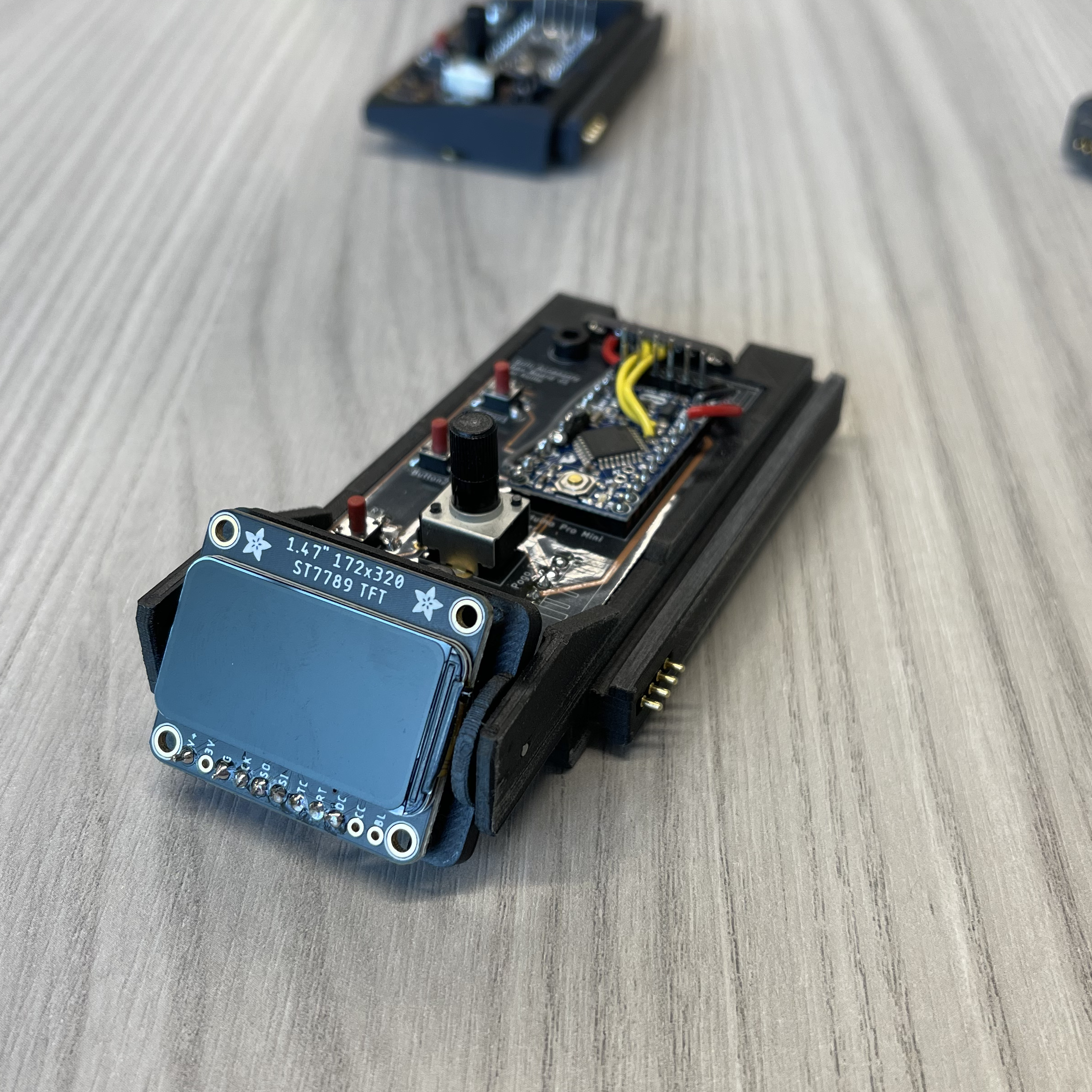
Accessory Interface Prototype v1

Motor Driver

Arduino Pro Mini 5V
Pogo Pin Contacts
}
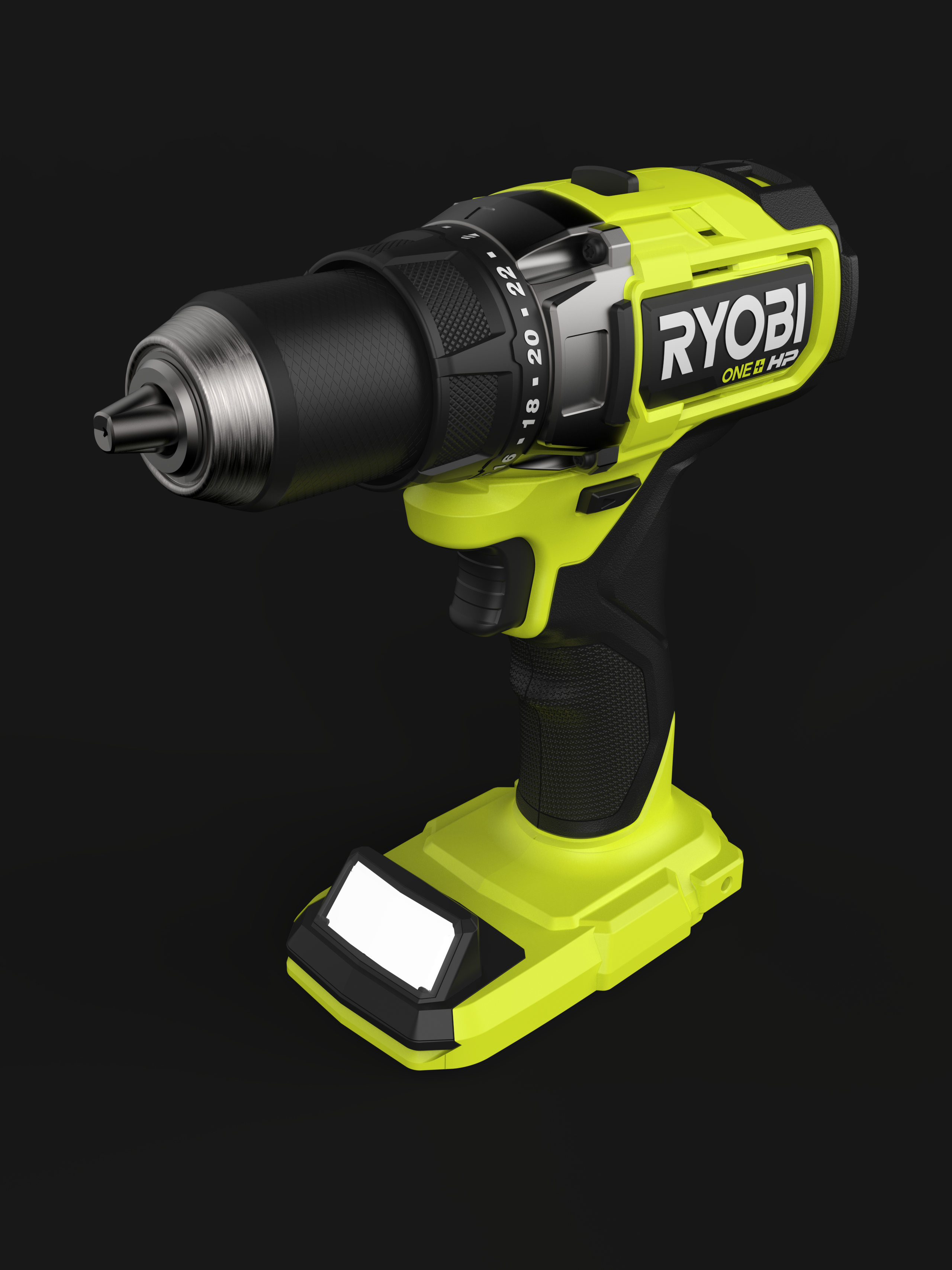
The drill was designed using parts from the Ryobi P215. For ease of prototyping, the thought was adding an Arduino Pro Mini (5V variant) and motor driver to quickly simulate a brushless tool with a motor controller and the included functionality of communication over data pins. This concept makes more sense on brushless tools as they already contain PCBs for driving the motor.
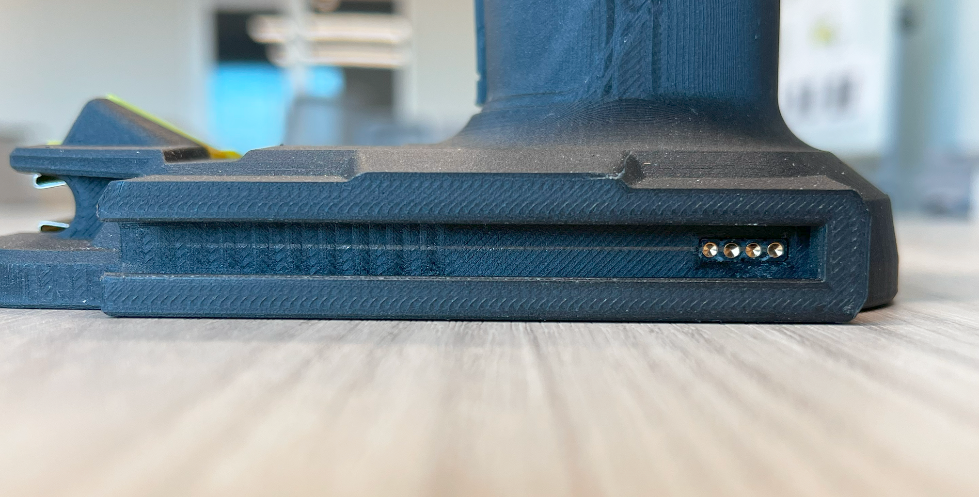
The interface to receive accessories was placed on the side of the battery foot. The thinking here was that the battery foot is a fairly standardized geometry, so it would be easy to translate to additional tools. Four pogo pins are located at the end of the “rail” that supply power, ground, and bidirectional communication.
In additonal to the drill, I worked on a series of powered and non powered accessories:
Magnetic Parts Tray
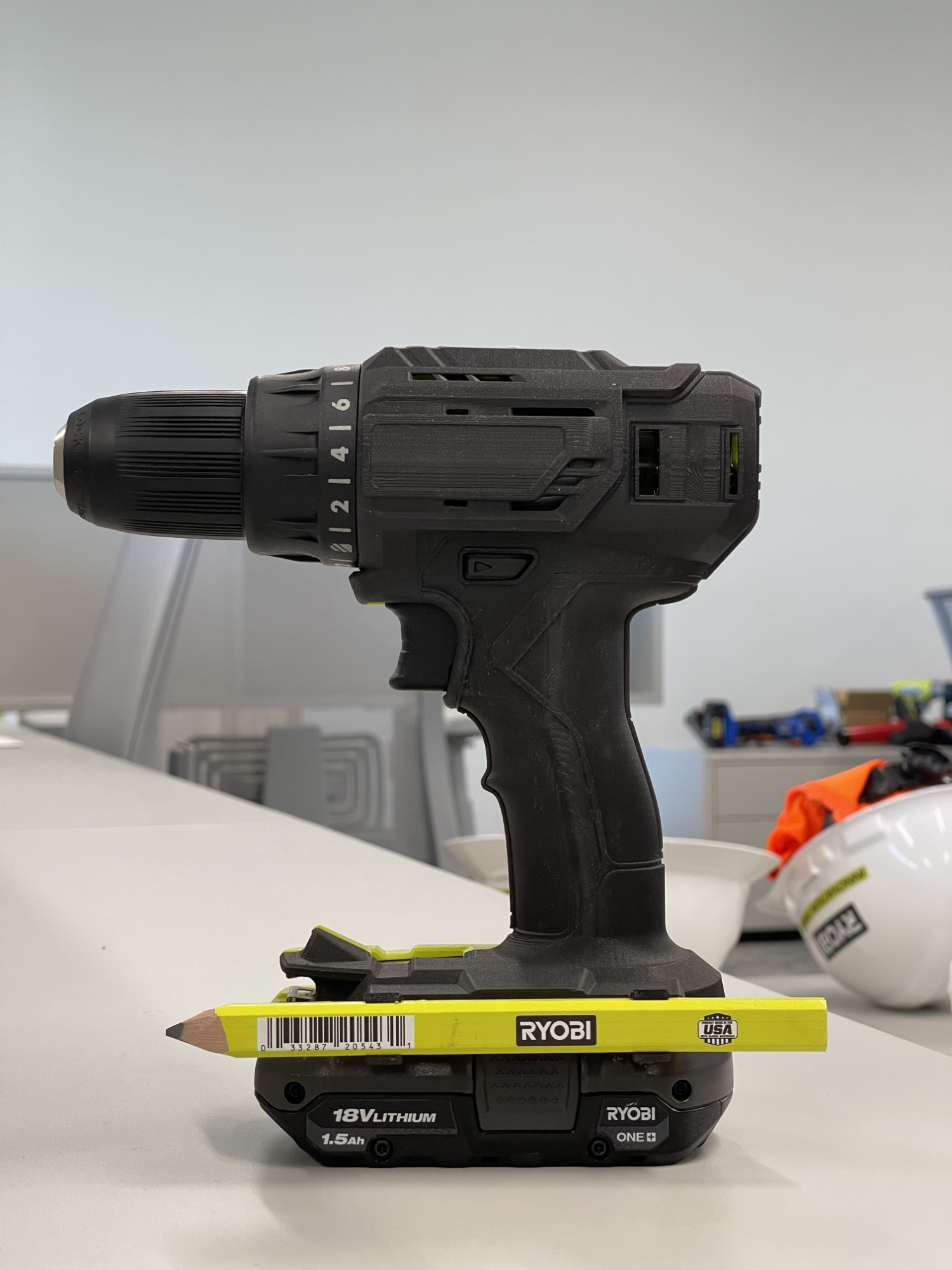
Carpenter's Pencil Holder
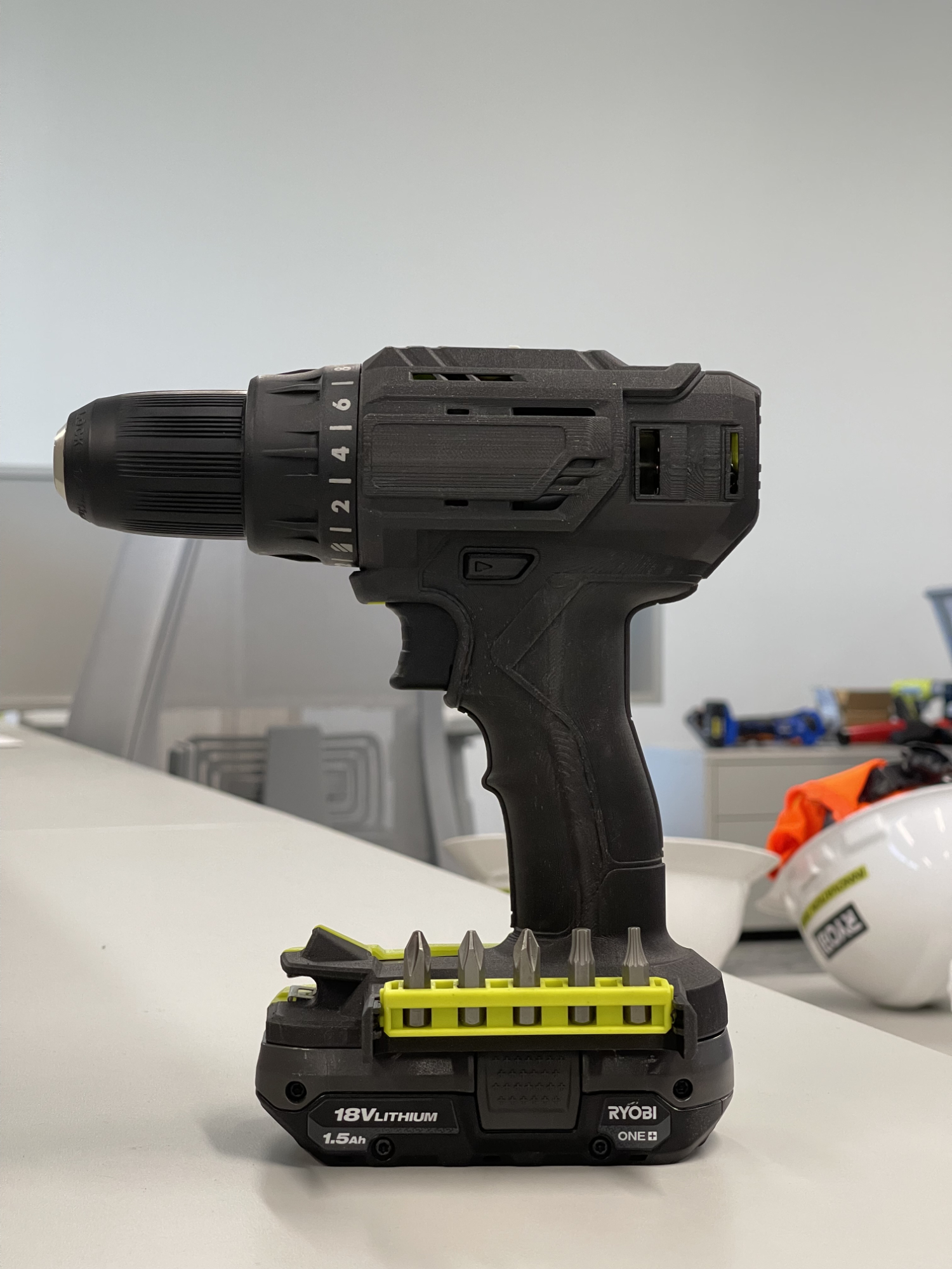
Bit Bar
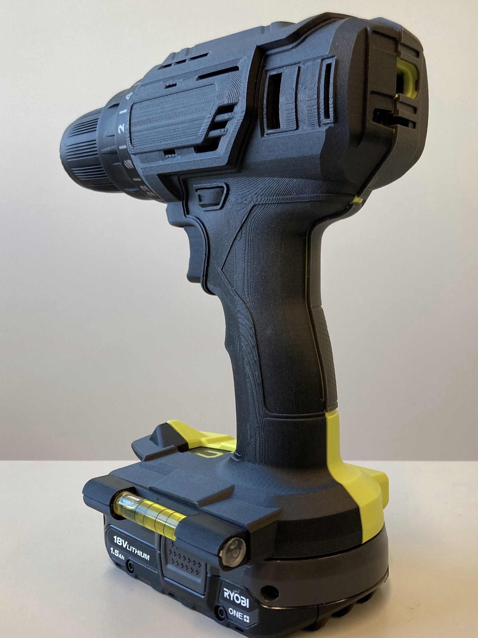
Bubble Level
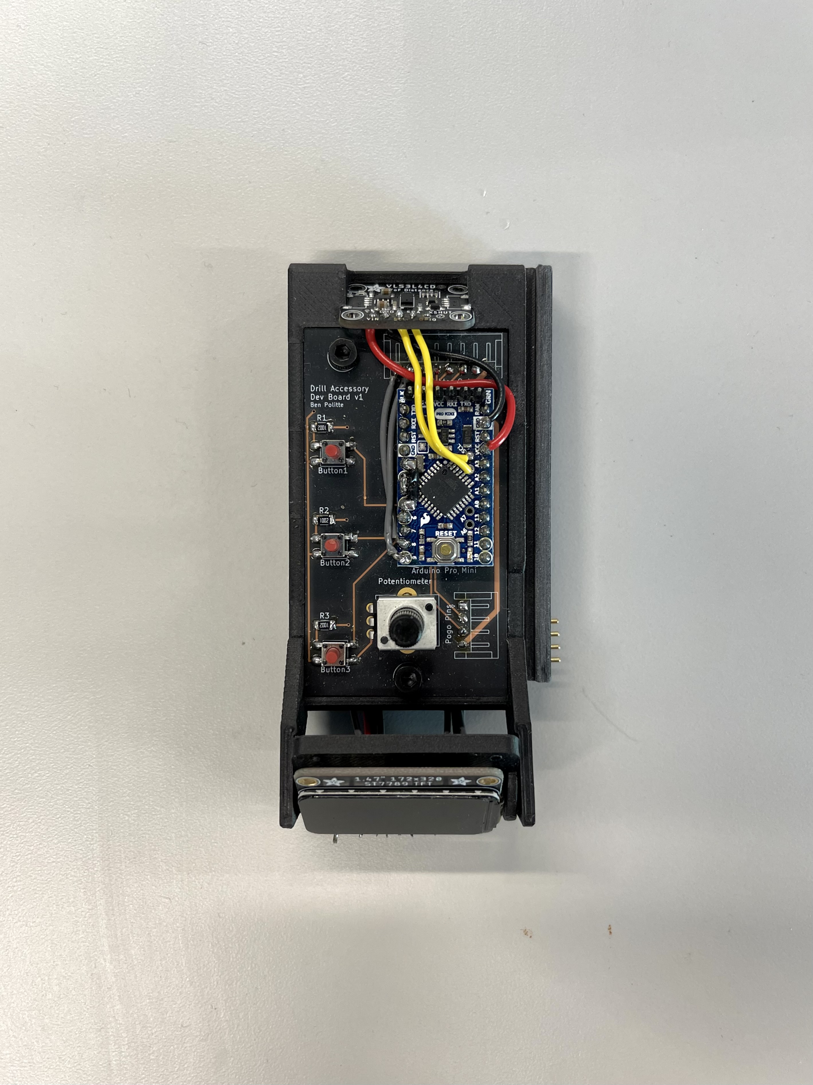
Universal Accessory Dev Board
On the accessory side I built a standardized accessory dev board that could be used in some different scenarios. This board housed an Arduino Pro Mini (5V variant), 3 buttons, a potentiometer, and pinouts connected to various pins to add things such as a display.
A standard 3D printed accessory was also developed to house the dev board.


Max Speed Adjustment
Using the potentiometer on the accessory, you can adjust the speed of the drill when the trigger is fully pressed, meaning that the tool remaps the whole trigger.
Brighter Light
Having a panel of multiple LEDs allow for greater lighting in areas which may be hard to see.

Depth Sensing & Cutoff
This accessory adds functionality over the depth sensing drill prototype by allowing the user to set a target depth. When the tool reaches the target depth it will shut off, meaning you cannot drill any deeper.
Tool Lockout
Using a Bluetooth-enabled Feather board, we built a quick prototype that would connect to your phone and allow you to “lock” the tool, meaning that pulling the trigger wouldn’t engage the motor until unlocked.

Initial Research
In the initial round of 4 interviews, users were shown all powered & non-powered accessories. In the second round of 5 interviews, users were shown only the top non-powered accessories: bit bar, level, and magnetic tray.
User Feedback
Non-Powered Accessories
- Users were most interested in a bubble level that was visible from the back and side of the drill with horizontal and vertical leveling, though they did not seem to have a strong preference on this being built in verses an accessory
- Users had mixed reception to the magnetic tray in terms of need for it
- Users did not like the double row bit bar accessory due to its bulk and unnecessary capacity, however users responded more positively to the single row bit bar accessory due to its slimer profile
- Users struggled to remove bit bars from the bit bar case itself and thus saw limited functionality with swapping the bit bar itself verses just the bits
- Users did not find value in the belt clip receiver or carpenter’s pencil accessories
Powered Accessories
- Users were hyper-focused on how far out to the side the powered accessories were, primarily due to concerns of durability
- Users always want a light on the drill – the functionality of at least one light should not be removable (brighter light still a potential)
- Users interviewed did not have a need for a max speed limiter since the drill has a variable speed trigger (all fairly advanced DIYers)
- Users had mixed reception to the depth control attachment – all noted it was a need, but some would rather keep taping their drill bits to measure depth instead for simplicity / familiarity
Module Brainstorm
A brainstorm was held within the team I work on of different accessories that could make sense:
Bigger Concepts To Explore
- Dust Management
- Passive Storage of Accessories
- Personalization of Tools
- Wifi Connectivity
- Haptic Feedback
- Universal Controller (App?)
Moving Existing Features To The Interface
- Alternate Belt Clip – Could integrate with LINK system?
- Storage for small accessories (pencils, bits, etc.)
- Hybrid power option (run on either AC or DC)
- Laser Guide
- Safety sequence for lights – Adding the ability to strobe our existing lights
- Adjusting settings of tool for certain jobs/materials
Pro-Focused Features
- Enumerating Battery Life
- Location Tracking
- Tool Locking
- Logging info such as how many holes have been drilled or how long a cut was
- Tether to the user for when working on a roof
- Mounts/Bases for existing tools
Existing Tools That Could Be Stored On-Tool
- Stud Finder
- Tape Measure
- Multimeter
- Mini Fan
- Sanding Block
- Walkie Talkie
- Notepad
- Glue Sticks
New Features
- Blower/Air assist clean around cut or act as vacuum
- Hole Placement – Communicate if you need to move in the x or y direction to drill a grid of holes
- Add USB-C port to charge battery
- Communicate when their tool cuts off (thermal, kickback, something else)
- Remote vacuum start/stop when tool is running
- Battery indication on LINK cases
- Music control
- Laser projection AR features
- Bit age detection
- Knot detection
I wanted to quickly highlight my mentality when I was thinking about modules for the different tools. I first started framing this idea similar to a hot shoe on a camera—having an attachment point on the camera for items like a larger flash or radio remote. These are additions that are vital for some applications, but for many people, they won’t ever be used because the camera itself is enough to fill their needs. The same idea should be applied to this accessory interface. I’m not suggesting the remove the standard LED from the tool or make it so that you cannot change the orbital action on a jigsaw without installing a module to save cost on the bare tool. Rather, creating different modules that can take a tool from something designed to be everything a beginner would need, to a tool that meets the user at their current skill level. Tailored to provide a better experience for the types of tasks they’re likely to do. With that I think that all the ideas regarding moving existing features to the interface are not good ideas.
Prototype v2
Goal
Explore the concept of a front-mounted accessory. Focus on the form and interaction of connecting the accessory to the tool.
Why
Without taking the prototype further on the functional side — as we can communicate that with the first product—this lets us push the form further to give users a better representation of what a final version could feel like. This also gives us the opportunity to see where this concept could fail when implemented in an actual product.
What I Focused On
- Form – This was designed to be a single effort into pushing what this accessory interface could look like
- Locking Interface – Work was put into thinking about if there is a way to secure the accessories beyond having a friction fit
What Was Less Important
- Functionality – Minimal effort was put into building accessories that would be functional from a prototype perspective
- Costing – Costing was not a judgement criteria for competing concepts during the development of this prototype
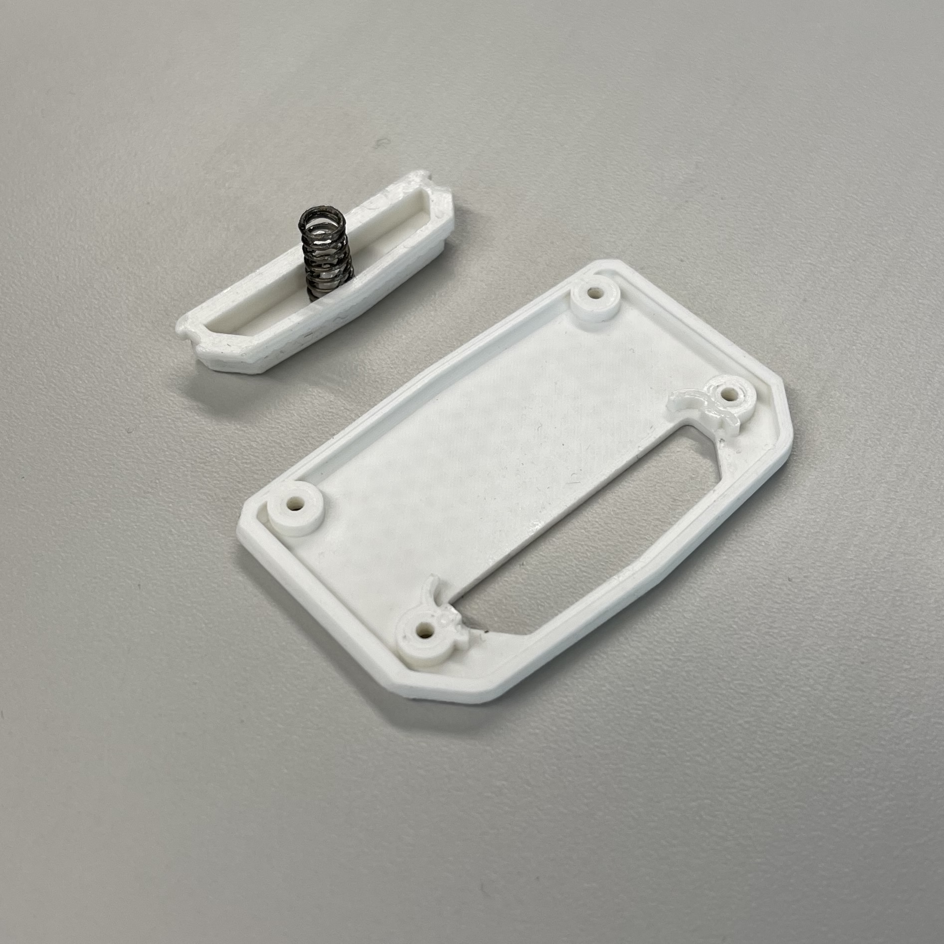
Rev 1
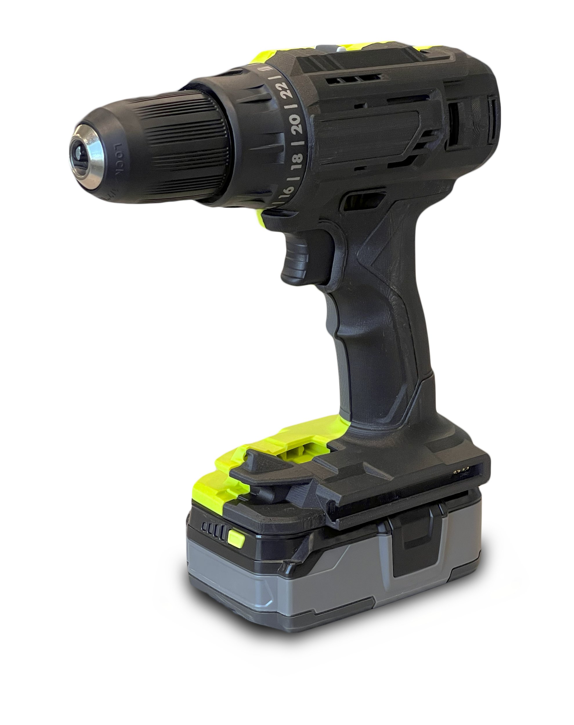
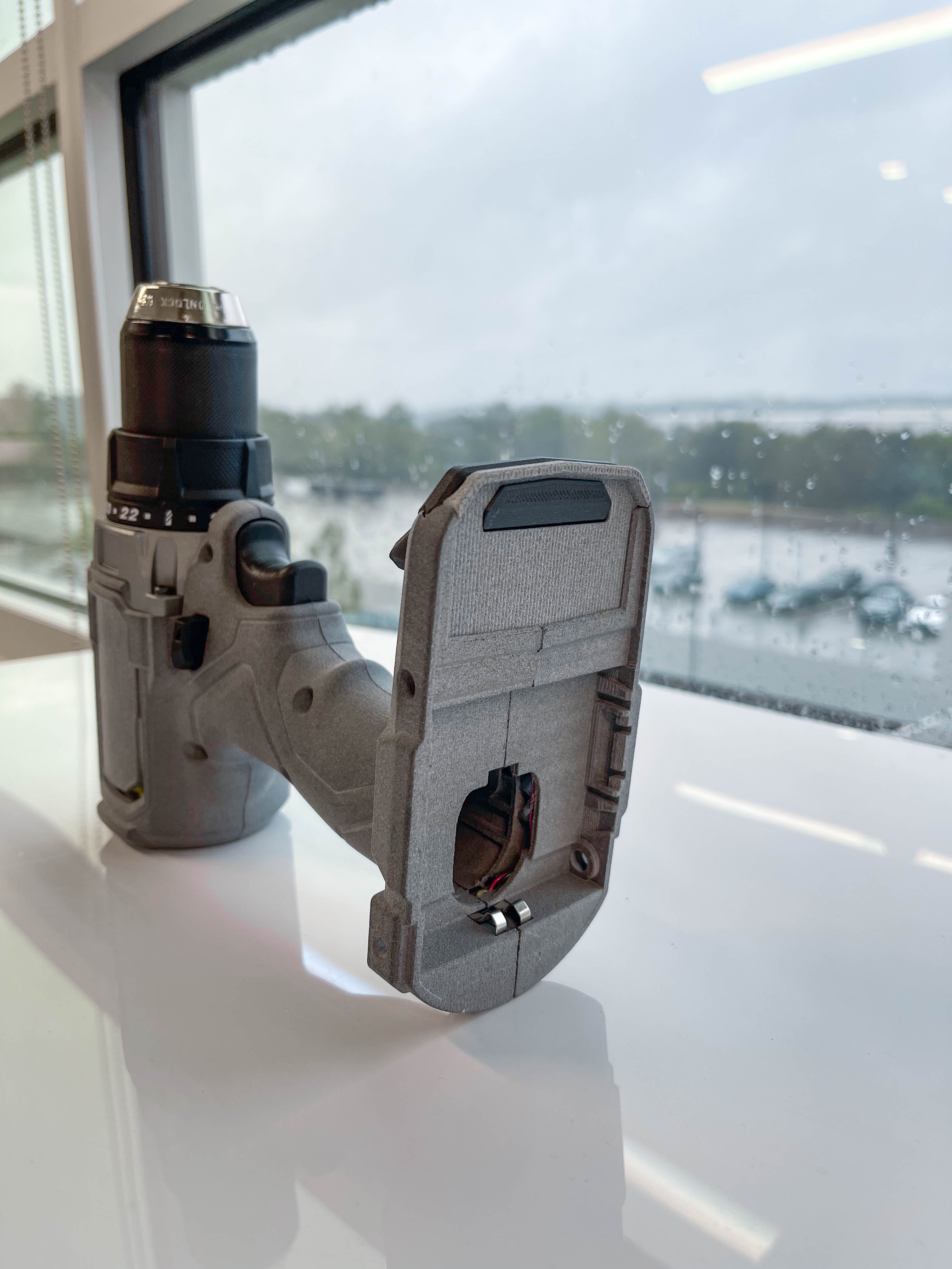
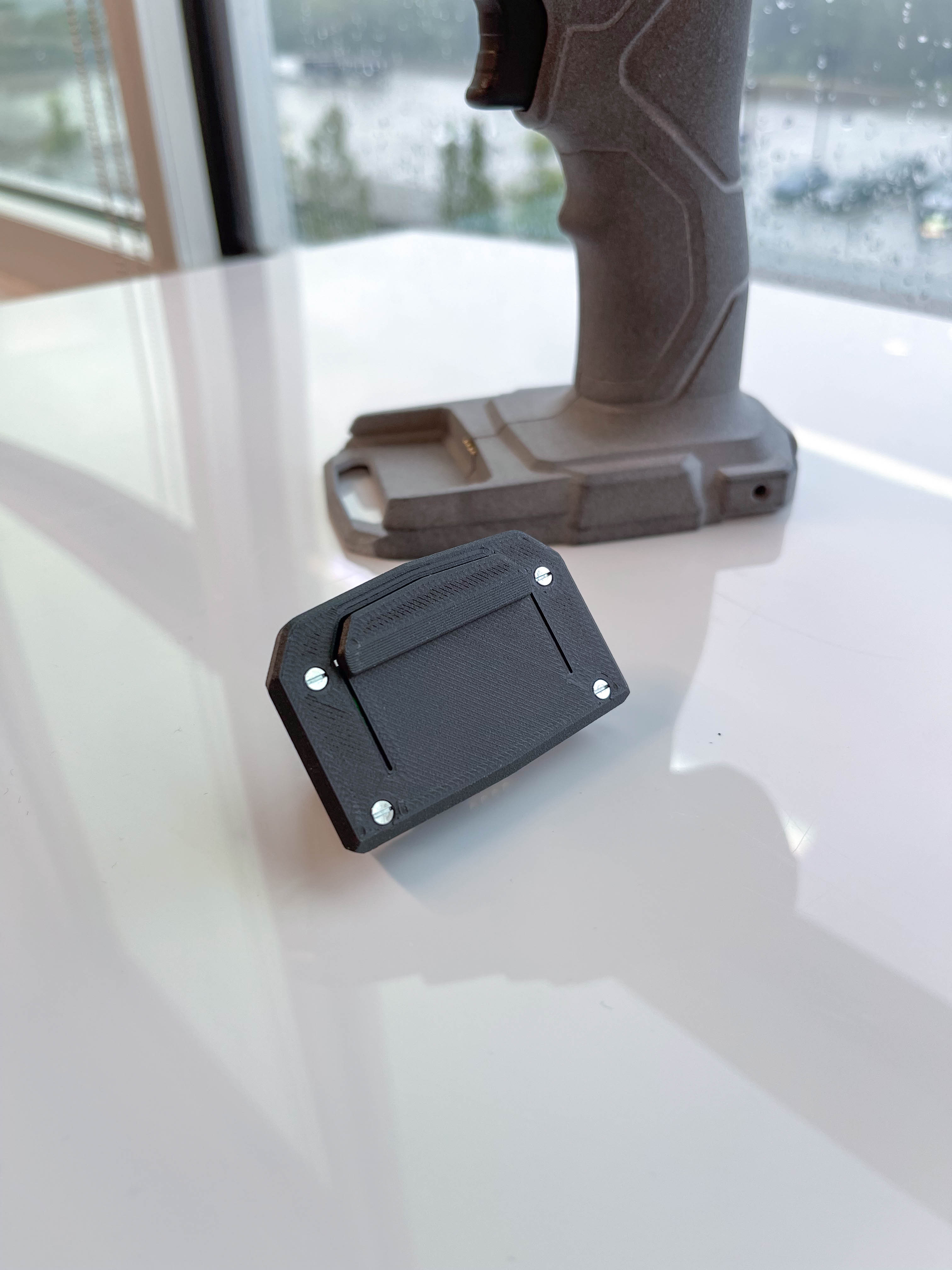
This was the initial design for the front interface. This utilizes a spring clip on the accessory that locks into a tab on the bottom of the foot; meaning that to remove an accessory the battery must be removed to push the clip with your fingers.
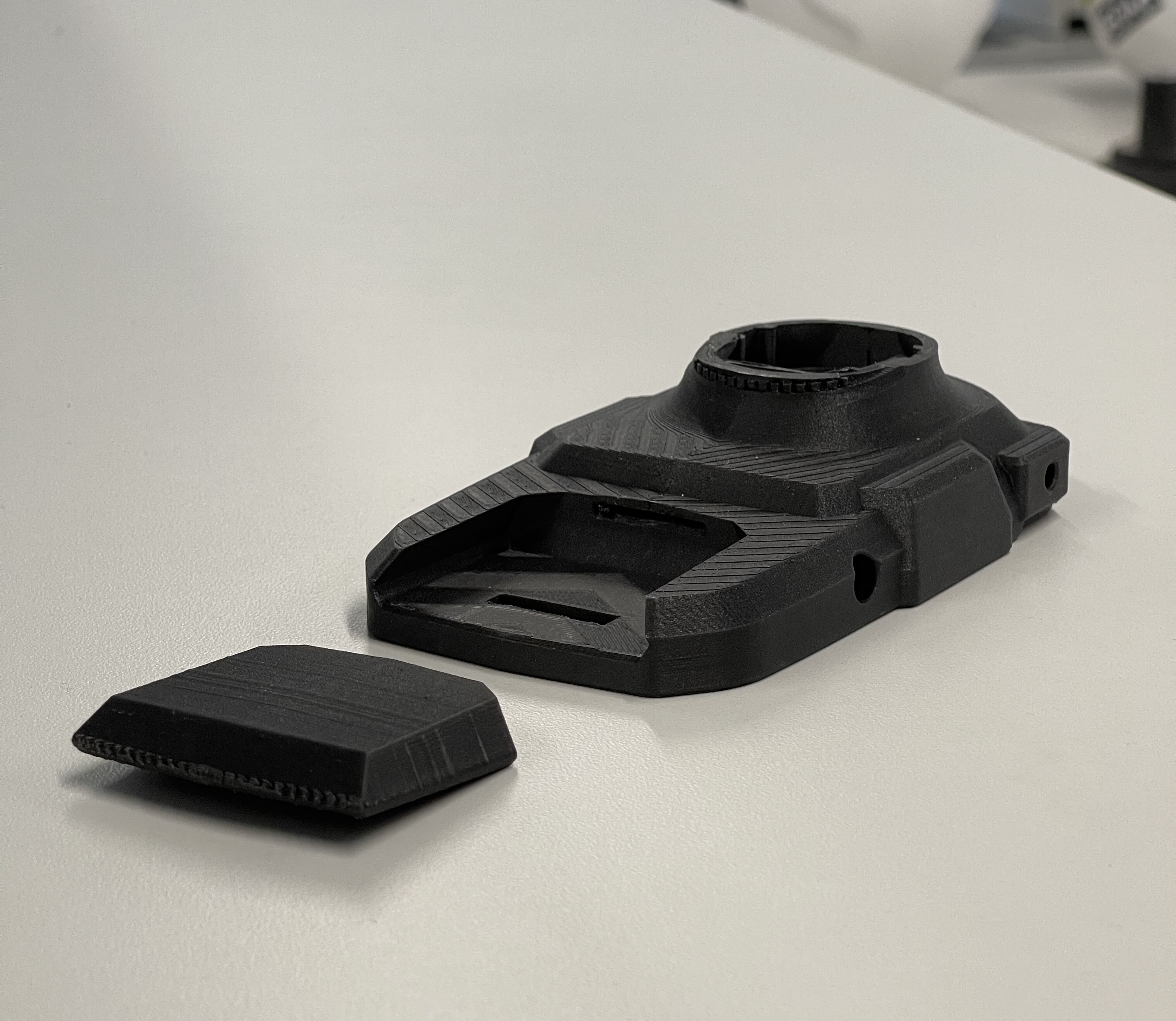


Rev 2
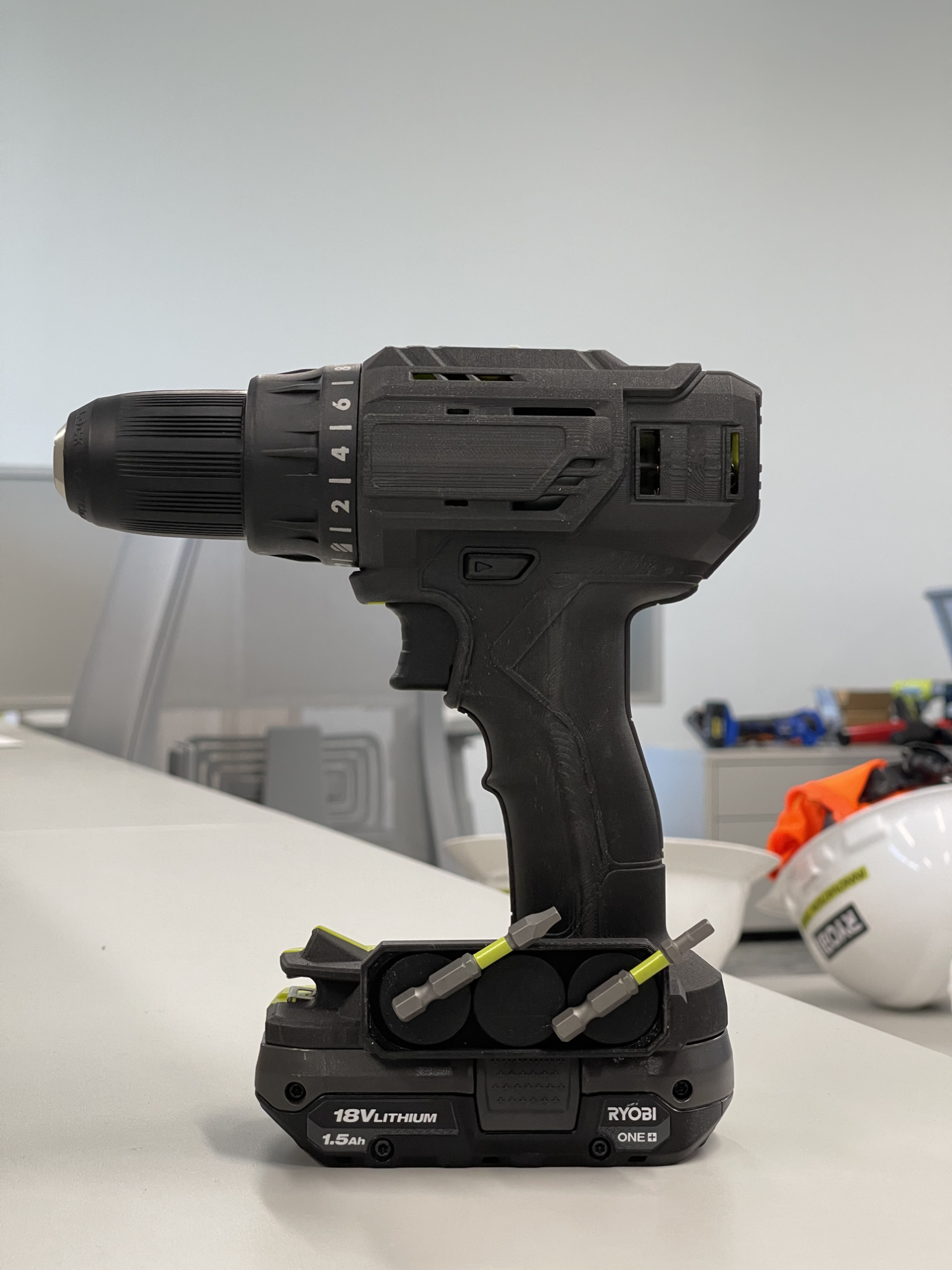
Rev 2 fixes some of the issues with the original version. For starters, it was hard to unlock and remove the accessories on the original version. To fix this a larger button is now used and I changed to having a dedicated button with a track to follow and spring. The accessories in Rev 2 are also larger than the original; being both wider and longer. In this current version the front on the accessory is being used by the button so electronics cannot fill the whole footprint. Three different sizes of accessories were also designed: a standard size that follows the contour of the foot, an extended height size that bumps upwards, and a panel size designed to house a series of LEDs.

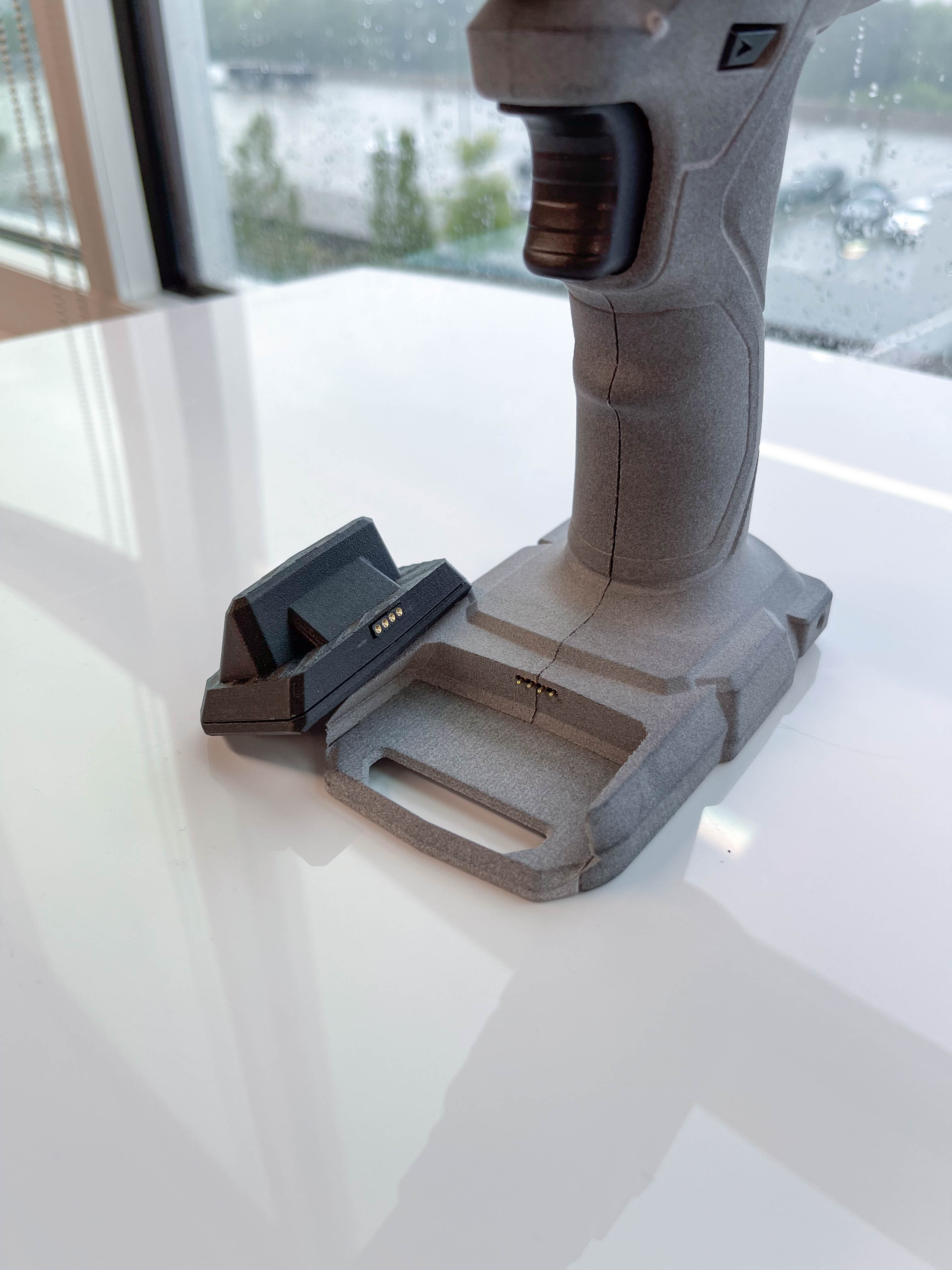
Rev 3
Rev 3 was made to show a semi-functional version of the front-accessory concept. It has pogo pins on the front of the housing that are connected to the led pins in the PBLDD01 PCBA and an accompanying LED module, meaning that you can attach/remove a working LED module. With how it’s made though, this is the only accessory that would work.
Other minor changes were made to make this version easier to build and less likely to break. The foot was updated to have a central floor that is captured by the housing. This was implemented to reduce the likelihood that the plastic in front of the lock port would break. The accessories have also gone back to a plastic spring clip built-into the bottom housing.